THz near-field scanning system

TeraCube
M2

A fiber-coupled, fully automated platform for micron-scale THz imaging on large areas. It records a full time-domain transient at every pixel, keeps the probe at constant distance on uneven surfaces, and runs as a laser class 1 instrument.

Probe tip above a calibration sample Transmission
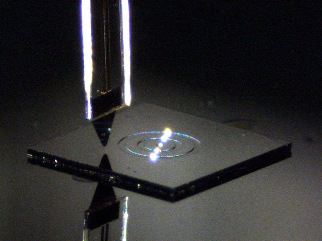
Photograph of a TeraSpike near-field probe tip held just above a glass calibration sample with a concentric ring structure; the THz emitter is visible below the sample.
TeraSpike detector above the sample, THz emitter below — the transmission geometry of the TeraCube M2.
0.05–4 THz
Spectral range
10 ms
Per full transient (min.)
18 × 18 cm
Max. scanning range
Class 1
Laser safety, normal operation
How it works

Fiber-coupled from laser to probe tip.

The femtosecond laser, the optical delay and the data acquisition sit in a separate time-domain spectroscopy unit. Two fibers carry the light to the scanner head and the THz emitter — there are no free-space beam paths to realign.

TeraCube M2 — signal chain Schematic
TDS UNIT fs fiber laser · 1550 nm fast-scan delay · 5–200 ps full transient per pixel no lock-in, no chopper encoder input · sync fiber SCANNER HEAD SHG → 780 nm probe excitation motorized focus & mirror optical distance sensor TeraSpike probe sample Tx THz emitter (M2) XYZ STAGE · 18 × 18 cm · ≤ 100 mm/s position-synchronized acquisition OUTPUT E(t) at every pixel amplitude · phase · spectral maps topography-corrected
01 · Generate

Full transients, fast

The TDS unit scans the optical delay continuously and records the complete THz waveform — 5 to 200 ps window, 50 fs step. No lock-in amplifier, no chopper: a full transient takes from 10 ms, typically 10–30 ms depending on time window and averaging.

02 · Probe

A microprobe in the near field

A fiber-coupled second-harmonic unit converts the 1550 nm laser to 780 nm and gates the TeraSpike probe. Motorized focus and mirror align the beam on the tip from the software, guided by the live photocurrent and camera image.

03 · Scan

Position-synchronized

The sample moves under the fixed probe in continuous motion. Stage encoder positions go straight to the TDS unit, so every waveform is tagged with its XYZ coordinate — no stop-and-go, no position guesswork.

Configurations

Transmission or reflection.

Both configurations share the scanner platform, the TDS unit and the software. They differ in where the THz pulse comes from and which probes are used.

TeraCube M2 · Transmission

Highest resolution, quantitative sheet resistance
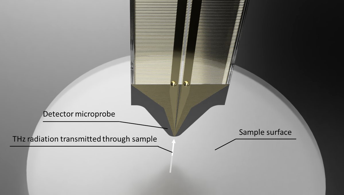
Rendering of a TeraSpike detector microprobe tip above a sample surface, with THz radiation transmitted through the sample from below.

A fiber-coupled emitter below the sample launches the THz pulse; a TeraSpike detector samples the transmitted field a few to some tens of micrometres above the surface. The sample is scanned between the fixed emitter and detector.

  • Best choice for the highest spatial resolution on THz-transparent samples
  • Preferred for sheet-resistance mapping: small distance variations are mostly uncritical
  • Detector probes from the TD-800-X and TD-800-Z series
TeraCube M2-R · Reflection

Depth information and opaque samples

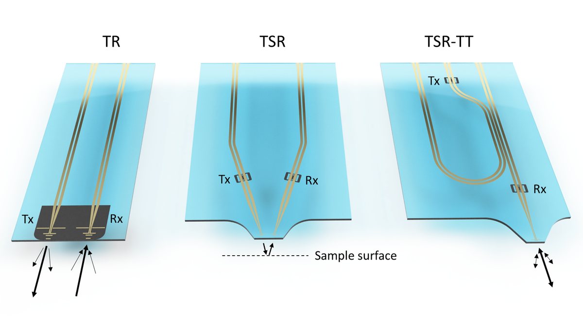
Renderings of three transceiver probe types — TR, TSR and TSR-TT — with emitter and receiver switches near the tip above a sample surface.

A transceiver probe carries emitter and detector on one tip. A second fiber-coupled SHG unit and beam path drive the emitter switch; its bias is set directly from the TeraCube software.

  • Time of flight gives depth — inside packages, coatings and layer stacks
  • Access to samples that are not transparent to THz
  • Transceiver probes TR (volume inspection) and TSR (high contrast at 150–350 µm stand-off)
System functions

Built for unattended mapping.

Set up once, then let the system follow the sample: preview, select, approach, map.

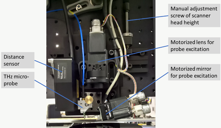
Photograph of the scanner head with labels: manual height adjustment screw, motorized lens and motorized mirror for probe excitation, distance sensor and THz microprobe.
Scanner head: THz microprobe, optical distance sensor, motorized lens and mirror for probe excitation.
  • Topography-adaptive scanning. An optical distance sensor (±0.5 µm) maps the surface first; the THz map then follows it at constant probe-to-surface distance — on structured, tilted or bent samples.
  • Preview and select. A fast topography preview scan lets you pick high-resolution areas interactively.
  • Software-assisted approach. Probe-tip approach to the surface is automated and interactively controllable.
  • Remote beam alignment. Motorized focus and mirror, live photocurrent display and a camera view of tip and sample.
  • Measurement automation. Single transients, multi-position transients on raster or point lists, area mappings — peak values or full trace maps.
  • Data you can use. Export as plain text or Matlab-compatible files; THz data analysis software for filtering, frequency-domain maps and statistics included.
Technical specifications

Technical data.

Values apply to TeraCube M2 and M2-R unless stated otherwise.

ParameterValue
THz measurement
Optical system constructionFiber-coupled
Spectral range0.05–4 THz
Data acquisitionFast-scan, full time-domain transient per pixel
Min. scanning time per pixel10 ms per full transient (5 ps window)
Time-domain scanning range5–200 ps
Time-domain step resolution50 fs
Laser sourcefs fiber laser, 1550 nm; fiber-coupled SHG for 780 nm probe excitation
Scanner
Maximum sample size (x, y, z)20 cm, 20 cm, 1 cm
Maximum scanning range (x, y, z)18 cm, 18 cm, 3 mm
Maximum scanning speed (x, y)Up to 100 mm/s
Bi-directional repeatability (x, y, z)±0.1 µm, ±0.1 µm, ±0.15 µm
Distance sensorOptical, ±0.5 µm
Delivery
Microprobes includedSet of 5 TeraSpike probes, freely chosen (M2: TD-800-X / -Z series)
SoftwareTeraCube control software, THz data analysis software
Data exportPlain text, Matlab-compatible
Laser classificationClass 1 in normal operation and maintenance*

* With laser-safety package installed; class 3R applies only during service by Protemics personnel. Laser certificate available on request. Default probe set if not specified otherwise: 1× TD-800-X-HR, 2× TD-800-X-HRS, 1× TD-800-X-HR-WT, 1× TD-800-X-HR-WT-XR.

Laser safety

Class 1 — no laser lab needed.

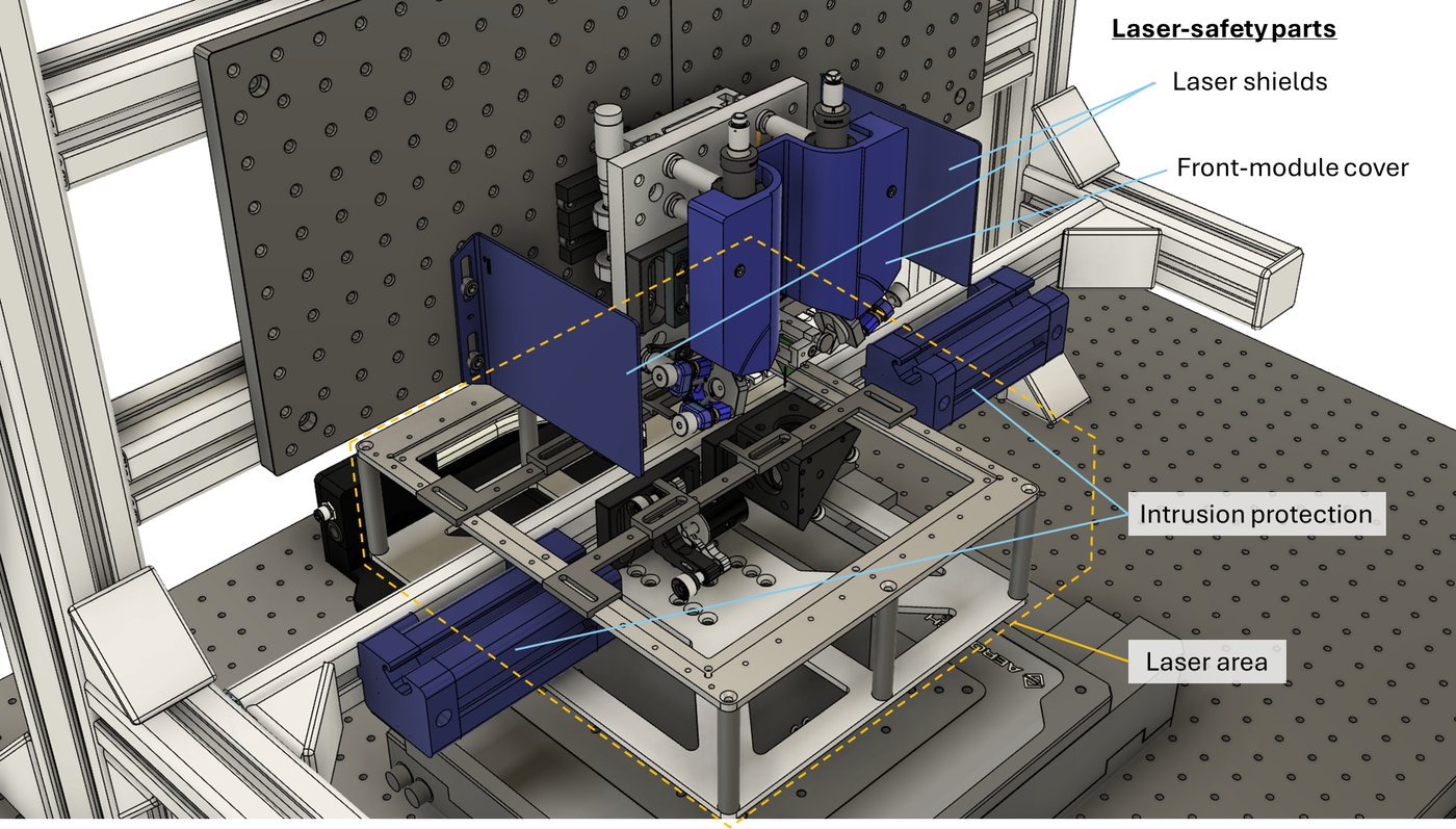
Laser shields, a front-module cover and an intrusion protection around the scanning table enclose every beam path. In normal operation and maintenance the TeraCube M2 meets class 1 limits: no laser safety officer, no protective eyewear.

ModeNormal operationMaintenanceService
Performed byOperatorOperatorProtemics
Laser class113R
Safety glassesNoNoYes
CAD rendering of the inner scanner with laser shields, front-module cover and intrusion protection marked, and the laser area around the scanning table outlined.
Laser-safety parts inside the scanner unit; the dashed line marks the laser area.
See it in action

Picoseconds, mapped.

Because the TeraCube M2 records the full waveform at every pixel, a single mapping can be replayed as a movie of the THz field propagating across an on-chip structure.

TeraCube M2 · on-chip THz near-field imaging
Footprint & installation

What arrives — and what your lab needs.

Protemics engineers install the system on site and train a dedicated operator. Space and site conditions are checked together with you before delivery.

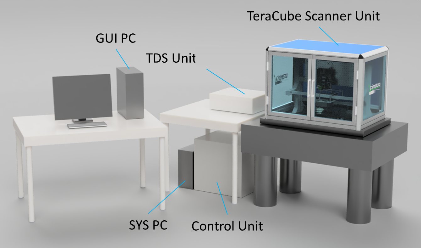
Rendering of the complete installation: scanner unit on an optical table, TDS unit, control unit, system PC and GUI PC with monitor.
System components: scanner unit on an optical table, TDS unit, control unit, PCs.
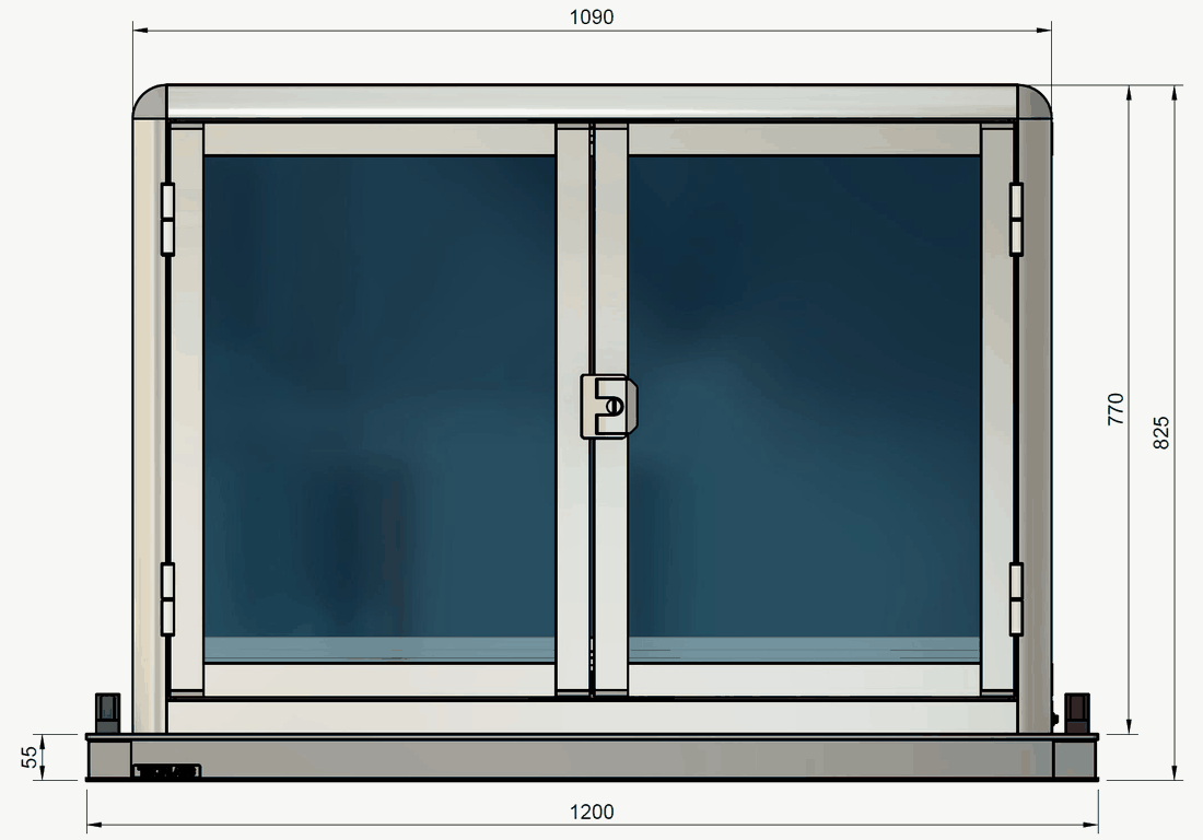
Front-view technical drawing of the TeraCube M2 housing: 1200 mm baseplate width, 825 mm total height.
Scanner unit, front view (mm).
Components & dimensions
Scanner unit
1200 × 750 × 825 mm³ (W × D × H), plus handles
TDS unit
180 × 450 × 530 mm³; fiber to scanner ≤ 2 m
Control unit
700 × 700 × 892 mm³; within 1.5 m of the scanner
User PC
Midi tower, up to two 24–26″ monitors
Site requirements
Placement
Vibration-damped optical table (VC-C), min. 75 × 120 cm, 120 cm free height
Power
230 VAC ±10 %, 50 Hz (100–240 VAC, 50/60 Hz on request); typ. 300 W
Environment
10–30 °C, ±2 °C during measurements; < 65 % r.h., non-condensing
Service
Installation
On site by Protemics engineers, including operator training
Customization
Open lab platform — probe set and configuration matched to your application
Maintenance
Optional yearly service package with replacement probe tips and maintenance visits
Where it's used

From metamaterials to the package.

Thin-film inspection

Sheet resistance & 2D materials

Contactless conductivity maps of transparent conductors, metal meshes, graphene and doped layers — wafer-scale, at micrometre resolution.

Sheet resistance imaging →
Chip testing

Chip & package inspection

Reflection-mode imaging through mold compound and IC-authenticity testing — a TeraCube M2-R is in use at the University of Florida's F.I.C.S.

Chip & package inspection →
Terahertz research

Metamaterials & devices

Near-field distributions of resonators, waveguides, antennas and sensor surfaces — in amplitude, phase and time.

Metamaterials & plasmonics →
Non-destructive testing

Microstructures & layers

Semiconductor wafers, microstructures and layered polymer parts, inspected without contact or sample preparation.

Send us a sample →
Documentation

Downloads.

Ready to specify

Request a TeraCube M2 quote.

Tell us your samples and what you need to see — we'll propose transmission or reflection, the probe set and the configuration. A test measurement in Aachen is usually the best first step.