On-chip THz time-domain spectroscopy

TeraLineX_ultra

A device platform for on-chip THz time-domain spectroscopy. Instead of focusing a free-space beam onto the sample, the THz pulse is generated, guided and detected on the chip — so micro- and nanoscale samples far below the THz diffraction limit can be measured with high sensitivity, also at low temperatures and in magnetic fields.

TeraLineX_ultra · TD-800-CPS On-chip TDS
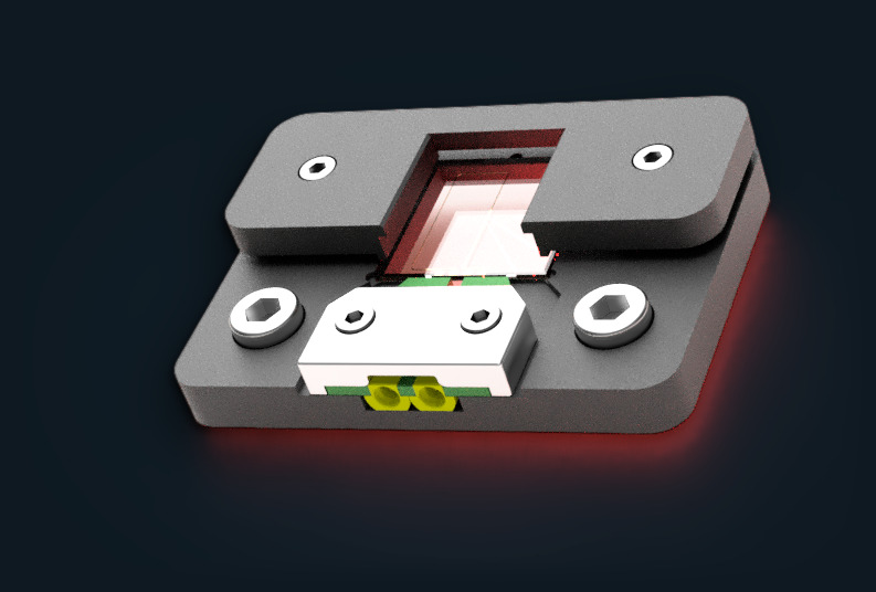
Rendering of the TeraLineX_ultra: dark-grey housing with a window over the chip, a white clamp and two SMP connectors at the front, with a red glow underneath.
1.1 – 1.4 ps
Pulse width (FWHM), examples
0 – 10 mm
Tx-to-Rx distance
5 · 10 · 30 µm
Photoconductive gap
Cryo · B-field
Compact, robust design
How it works

THz spectroscopy below the diffraction limit.

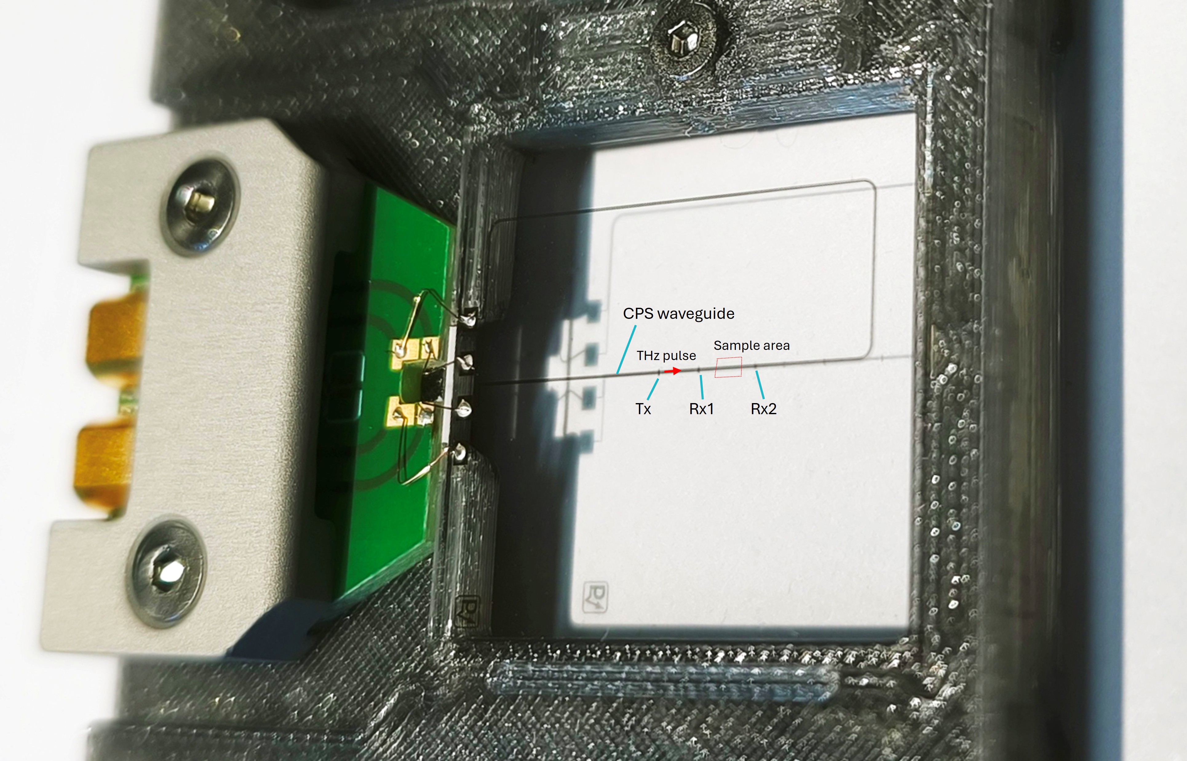
The TeraLineX_ultra is based on a low-loss coplanar stripline (CPS). Photoconductive switches embedded in the waveguide generate the THz pulse and detect it before and behind the sample area. Because the THz mode propagates along the chip surface, it interacts strongly with thin-film samples — devices and samples at the micron scale become accessible to time-domain spectroscopy.

Close-up of a TeraLineX chip on its green carrier board with two gold SMP connectors. Annotations mark the emitter switch Tx, detector switch Rx1 before and Rx2 behind a 5 mm long sample area, and the path of the THz pulse along the stripline.
Waveguide with three photoswitches. Tx generates the THz pulse; Rx1 detects the incident and reflected signal before the sample, Rx2 the transmitted signal behind it.
Key benefits

A sensor, not a beam path.

  • Highly integrated and sensitive waveguide-based THz-TDS platform
  • Reflection- and transmission-mode measurements on one chip
  • Compact and robust: ideal for small cryo chambers, low temperatures and high magnetic fields
  • Samples applied on exchangeable daughter-boards, flip-chip mounted onto the TeraLineX motherboard — cost-efficient and flexible
  • Configurable in substrate, coupling, number and position of detectors and line geometry; further configurations on request
Time-domain measurement performance

Picosecond pulses on chip.

Four example configurations, from a single-switch auto-correlation to transmission measurements on COP and fused-silica substrates. Measured with a fast-scan THz-TDS system as included in the TeraCube M2.

Single-switch auto-correlation of model TD-800-CPS-C-Y-0-0-0: sharp peak with 0.7 ps FWHM.
C-Y-0-0-0. Single-switch auto-correlation, 0.7 ps FWHM.*
THz pulse of model TD-800-CPS-C-Y-1-3-0 with a pulse width of 1.2 ps FWHM.
C-Y-1-3-0. COP substrate, Rx at 3 mm: pulse width 1.2 ps FWHM.
THz pulse of model TD-800-CPS-Q-Y-1-1-0 (fused silica) with 1.4 ps FWHM and a small substrate back-side reflection about 10 ps later.
Q-Y-1-1-0. Fused-silica substrate, dc-coupled: 1.4 ps FWHM; small substrate back-side reflection.
Full-cycle THz pulse of model TD-800-CPS-Q-N-1-1-0 with 1.1 ps FWHM and a substrate back-side reflection about 10 ps later.
Q-N-1-1-0. Fused-silica substrate, not dc-coupled (full-cycle pulse): 1.1 ps FWHM.

* Single-switch (transceiver) operation requires a fast-scan measurement scheme without lock-in amplifier.

Configuration

Configured to your experiment.

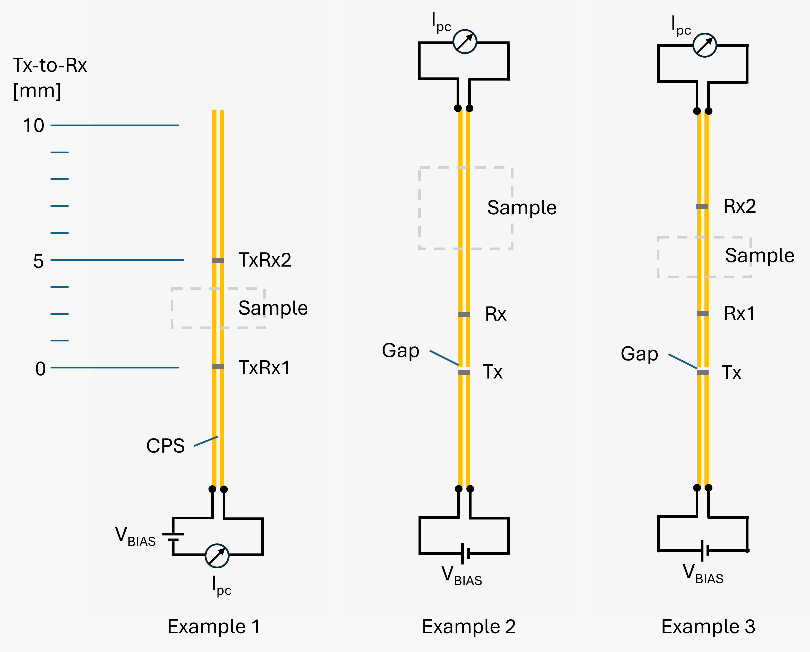
Each TeraLineX_ultra is built from six configuration variables. The model code lists them in order, e.g. TD-800-CPS-C-Y-2-3-7-M.

Pos.Configuration variableStandard options
ASubstrateC — COP (ZEONOR), 100 µm, n = 1.51
Q — fused silica, 1 mm, n = 1.97
BTx-Rx dc-coupling · received pulse formY — yes · half-cycle
N — no · full-cycle
CNumber of Rx elements0, 1 or 2
DTx-to-Rx1 distance0 … 10 mm
ETx-to-Rx2 distance0 … 10 mm
FLine width – spacing – widthL — 50-30-50 µm
M — 15-10-15 µm
S — 8-5-8 µm
Three example layouts along a coplanar stripline: Example 1 with transceiver switches TxRx1 at 0 mm and TxRx2 at 5 mm around the sample; Example 2 with Tx and Rx before the sample; Example 3 with Tx and Rx1 before and Rx2 behind the sample. Bias source and current meter connections are indicated.
Example layouts. 1: transceiver switches before and behind the sample (fast-scan only). 2: Tx and Rx before the sample (reflection). 3: Tx and Rx1 before, Rx2 behind the sample (reflection and transmission).
CCOP substrate, 100 µm
Ydc-coupled, half-cycle pulse
2Two Rx elements
3Rx1 at 3 mm from Tx
7Rx2 at 7 mm from Tx
M15-10-15 µm lines, 10 µm gap

Example: TeraLineX_ultra TD-800-CPS-C-Y-2-3-7-M. Other configurations on request.

Technical specifications

Technical data.

TD-800-CPSEmitter (Tx)Detector (Rx)
PC gap size30, 10 or 5 µm (line geometry L, M or S)
Dark current @ 1 V bias< 0.5 nA< 0.5 nA
Photocurrenta> 0.1 µA> 0.1 µA
Excitation wavelength700 … 860 nm
Avg. excitation power0.1 … 4 mW0.1 … 4 mW
Typical bias voltage9 V (THz measurement)1 V (optical alignment)
Connection typeSMP
SubstrateCOP (ZEONOR, Tg 163 °C), 100 µm, or fused silica (Tg > 1600 °C), 1 mm

a For a focus diameter of ca. 30 µm and a 10 µm PC gap; emitter at 9 V bias and 3–4 mW average excitation power, detector at 1 V bias as used for optical alignment.

Product details

  • Photoconductive THz-TDS chip with integrated overvoltage protection, optimized for pulsed excitation
  • Optional: replaceable daughter-board chips for sample application
  • Test certificate and manual
  • Dust-free, robust storage box

Accessories

  • TS Cable — SMP to SMA, with SMA-to-BNC adapter
  • TS Companion low-noise amplifier
  • Mounting and focusing units
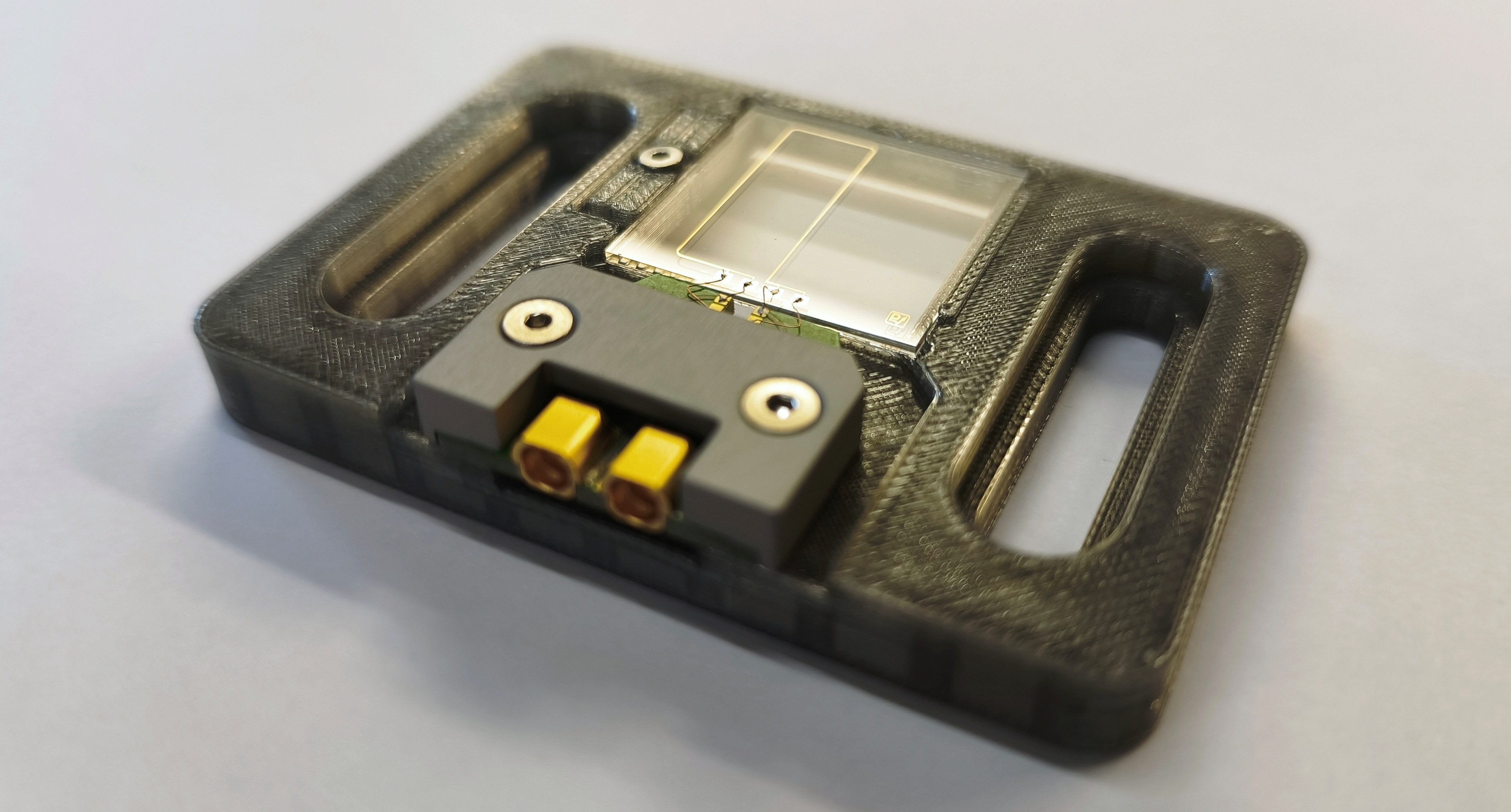
TeraLineX chip on a green carrier board with two gold SMP connectors, mounted on a translucent holder.
In research

Published with the TeraLineX.

Research groups use the platform for THz measurements on superconductors, graphene and thin-film conductors, at room and at cryogenic temperature.

All publications on waveguides & on-chip THz →
Ready to specify

Request a TeraLineX_ultra quote.

Tell us about your samples and measurement environment — temperature, magnetic field, available space — and the configuration you have in mind. We'll propose the layout and confirm the model code.