Low-noise current amplifier for THz sensors

TeraSpike
Companion

A transimpedance amplifier built for THz time-domain spectroscopy with photoconductive detectors and emitters, including the full TeraSpike probe range. It has inputs for Tx and Rx, an optical alignment mode, switchable bias and full electronic control, and keeps 40 kHz bandwidth at every gain setting.

TS Companion · LNA-40k-8E8 2 inputs
Photograph of the TS Companion amplifier: brushed aluminium housing with Protemics logo on a black mounting plate, two SMA input connectors and a 15-pin Sub-D control connector.
106 – 8×10⁸ V/A
Transimpedance gain
40 kHz
−3 dB bandwidth, every gain
Tx + Rx
Two isolated SMA inputs
Local / remote
Sub-D control bus, USB plug
Why a dedicated amplifier

Full bandwidth at every gain.

Conventional current amplifiers trade bandwidth for gain: at high transimpedance their bandwidth drops to the kHz range. That is acceptable behind a lock-in, but fast-scan THz-TDS records a complete transient within milliseconds. The TS Companion keeps its 40 kHz bandwidth from the lowest to the highest gain setting, so the waveform is not low-pass filtered when you turn up the gain.

Frequency response of the TS Companion for twelve gain settings from 1×10⁶ to 8×10⁸ V/A: all curves are flat up to about 40 kHz.
TS Companion. Frequency response for all 12 gain settings, 1×10⁶ to 8×10⁸ V/A.
Frequency response of a conventional current amplifier at 1×10⁷, 1×10⁸ and 1×10⁹ V/A: the bandwidth decreases strongly with increasing gain, at 1×10⁹ V/A it peaks around 1 kHz.
Conventional current amplifier. Bandwidth shrinks as the gain goes up, 1×10⁷ to 1×10⁹ V/A.
THz-TDS application

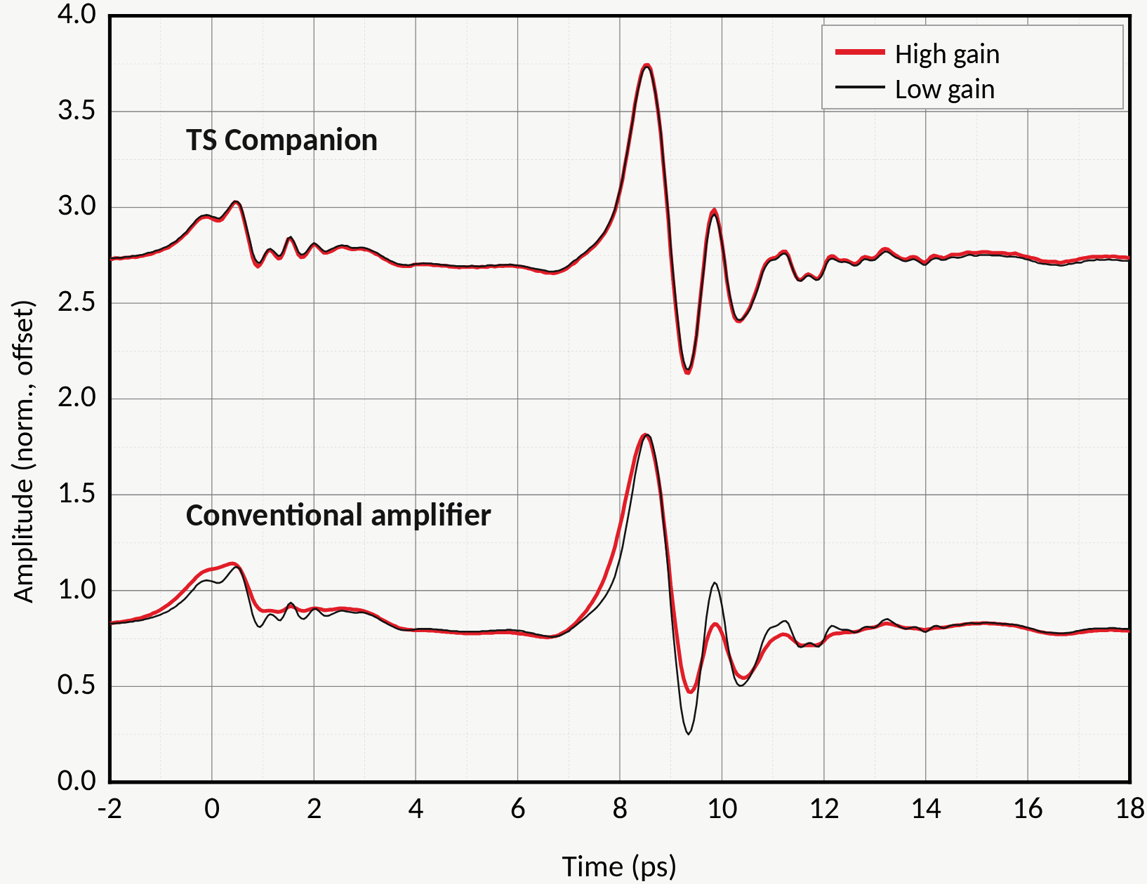
One transient, two gains.

The same THz transient recorded at high and at low gain. With the TS Companion the two traces coincide. With a conventional amplifier, the high-gain trace is visibly filtered: the main peak broadens and the following oscillation is damped.

Measured with a TeraSpike TD-800-TSR-TT.75 transceiver probe.

Two pairs of THz time-domain traces: for the TS Companion the high-gain (red) and low-gain (black) traces overlap; for a conventional amplifier the high-gain trace is broadened and its oscillation after the main peak is damped.
Built for THz-TDS

What a general-purpose amplifier doesn't have.

Inputs

Tx and Rx on one amplifier

Two isolated SMA inputs. The bias for each connected device is applied through the outer conductor of its input connector, so a transceiver probe needs no extra wiring.

Operating mode

Alignment ↔ THz

In alignment mode a 1 V bias is applied to the photoswitch: maximise the output signal to centre the excitation spot. In THz mode the bias is off and the probe works as a THz antenna.

Gain

12 settings, 1-2-4-8

1, 2, 4 and 8 per decade from 1×10⁶ to 8×10⁸ V/A, so you can work close to the best signal-to-noise ratio of your setup without saturating.

Signal path

40 kHz or 0.4 kHz, AC or DC

−3 dB bandwidth of 40 kHz for fast-scan acquisition, switchable to 0.4 kHz; AC or DC coupling. An LED signals overload.

Control

Remote, local or scripted

All functions are set through a 15-pin Sub-D control bus with logic levels (LOW ≤ 0.8 V, HIGH ≥ 2.4 V) — ready for system integration. A USB Remote Control Plug with Windows software and an optional manual control plug are available.

Supply

Wide supply range

Runs from ±5 to ±14 V (±12 V recommended) and provides an external bias supply for the connected THz devices of up to ±12 V, 120 mA.

Typical configurations

Three ways to wire a TeraSpike.

Pin and switch settings for each scheme are listed in the datasheet.

Scheme 01

Probe alignment

The probe is biased through the input connector and the generated photocurrent is amplified. Used to align the probe beam onto the TeraSpike photoswitch.

Scheme 02

THz measurement

The microprobe works as a THz antenna without bias; the amplifier converts its current into the measured THz signal.

Scheme 03

Transceiver operation

Input 1 biases the emitter switch of a transceiver probe for THz generation, input 2 reads the detector switch.

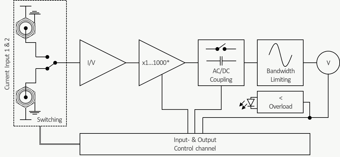
Block diagram: two current inputs with switching, I/V converter, gain stage x1 to x1000, AC/DC coupling, bandwidth limiting, output voltage and overload detection, all controlled via the input and output control channel.
Block diagram.
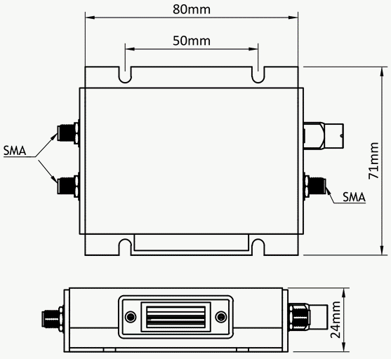
Dimension drawing: housing 80 mm by 71 mm including mounting plate, 50 mm hole spacing, 24 mm height, SMA connectors on both sides.
Dimensions: 80 × 71 × 24 mm³, 120 g.
Technical specifications

Technical data.

Model LNA-40k-8E8. Test conditions: VS = ±12 V, room temperature, load impedance 10 MΩ.

ParameterValue
Transimpedance gain*1×10⁶ … 8×10⁸ V/A, 12 steps (1-2-4-8 per decade)
−3 dB bandwidth*40 kHz for all gain settings, switchable to 0.4 kHz
CouplingAC / DC, switchable
Amplifier output voltage±12 V
Max. output current±40 mA
External bias supply for THz device inputs±12 V, max. 120 mA
Inputs2 × SMA jack, isolated; device bias via outer conductor
OutputSMA jack
Control interface15-pin Sub-D, logic LOW ≤ 0.8 V, HIGH ≥ 2.4 V
Indicator LEDOn: overload · Off: normal operation
Power supply voltage±5 … ±14 V (max.), ±12 V recommended
Power supply currenttyp. ±50 mA
Power supply connectorLemo series 0B, 3-pin · pin 1 GND, pin 2 −12 V, pin 3 +12 V
Dimensions · weight80 × 71 × 24 mm³ · 120 g
Operating temperature0 … 70 °C

* Gain range and bandwidth can be customized on request. Full pin assignments, control addresses and typical characteristics: see the datasheet.

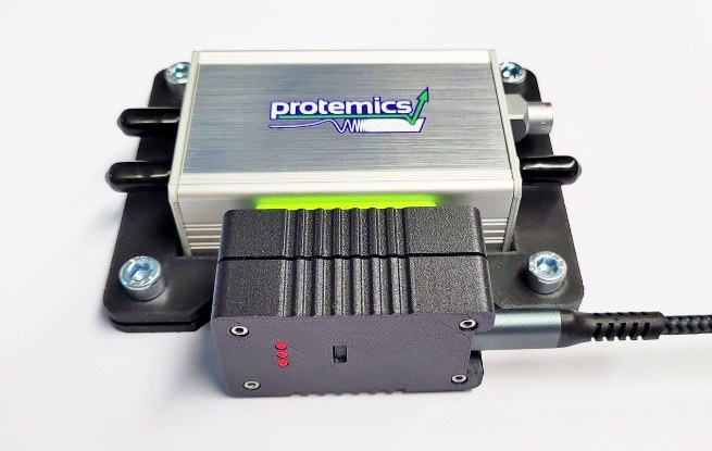
Photograph of the TS Companion with the black Remote Control Plug attached to its Sub-D connector and a USB cable.
Accessory

Remote Control Plug

Plugs onto the Sub-D connector and connects the amplifier to a PC via USB. The portable Windows application (Windows 10 or later, no installation) switches channels, modes, coupling and gain, and runs bias-voltage sweeps with automatic saving.

Applications

Documentation

Downloads.

Ready to specify

Request a TS Companion quote.

Tell us your THz system, detectors and acquisition scheme. We'll confirm the configuration or a customized gain and bandwidth range.