Photoconductive THz near-field transceivers

TeraSpike
Transceiver

Emitter and detector on one slim probe. The TR series brings near-field resolution to reflection mode — for samples that are large, complex or opaque to THz radiation.

TeraSpike TD-800-TSR.75 TRANSCEIVER
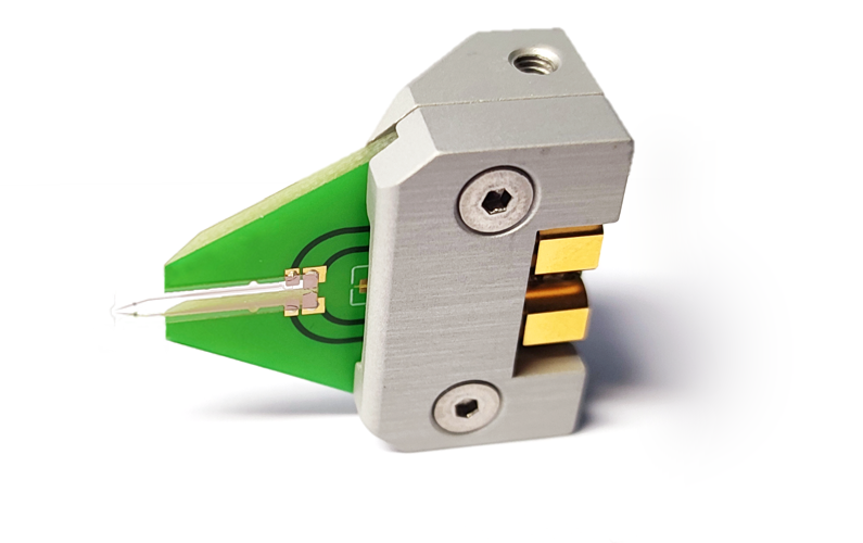
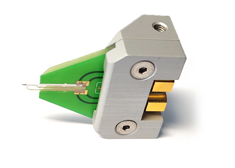
TeraSpike TD-800-TSR.75 transceiver probe: probe holder with two SMP connectors and the cantilever carrying emitter and detector antenna.
40–250 µm
Spatial resolution
up to 3 THz
Bandwidth
Reflection
Measurement mode
Select a transceiver

Three geometries, one idea.

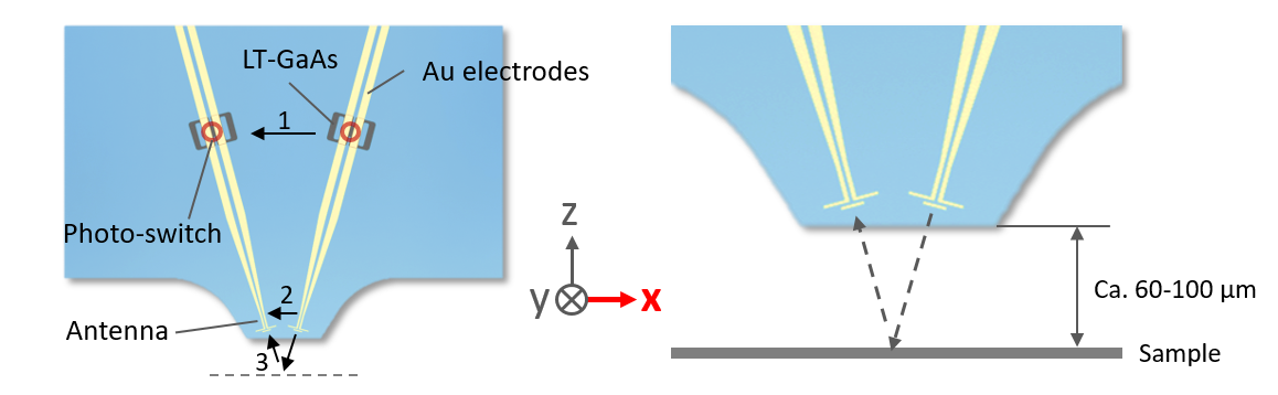
In conventional reflection setups, emitter and detector sit in the far field. TR probes put both into the near field of the sample: sub-wavelength resolution and the shortest possible THz transmission path.

ModelTSR-TT.75TSR.75TR.5
Spatial resolution40 µm100 µm250 µm
Antennas122
Incidence0°15°0°
Bandwidth2 THz3 THz1.5 THz
ModeReflection & transmissionReflectionReflection
Excitation wavelength700–860 nm700–860 nm700–860 nm

TSR-TT.75 — single antenna at normal incidence, the strongest choice for surface scanning at maximum resolution (details). TSR.75 — two closely spaced antennas at 15°, the widest bandwidth, for near-surface volume inspection (details). TR.5 — the entry point into reflection-mode volume inspection (details). All TR probes use the proprietary wave-trap design and the robust XR-type cantilever.

Reflection mode in the near field

Emit and detect at the tip.

TD-800-TR.5 — the first near-field transceiver

  • A pair of closely spaced photoconductive antennas: one generates the THz pulse, the other detects it.
  • Proprietary wave-trap electrodes suppress probe-internal reflection signals.
  • XR-type flexible PET cantilever for mechanical robustness at close sample distance.
  • Suited for non-destructive testing of solar cells, plastic parts with buried laser welds and fiber-reinforced materials.
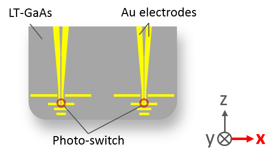
Antenna design of the TR.5 transceiver probe: emitter and detector antenna side by side.
TR.5 antenna design: emitter and detector antenna side by side.

TR.5 electrical data

ParameterTR.5
Dark current @ 1 V bias< 1.5 nA
Photocurrent @ 1 V bias> 0.5 µA
Excitation wavelength700–860 nm
Average excitation power0.1–4 mW
Connection type2 × SMP

Each probe is individually tested and ships with a manual and test certificate.

Widest bandwidth

TD-800-TSR.75.

TR-series probes are mainly sensitive to THz field components transversal to the probe-tip axis (x).

TD-800-TSR.75 — near-surface volume inspection

Measurement scheme of the TSR.75: two antennas at 15° incidence.
Two closely spaced antennas at 15° incidence.

Technical data · TSR.75-PCS10-50

ParameterTSR.75-PCS10-50
Max. spatial resolution100 µm
Dark current @ 1 V bias< 10 nA (typ. < 1.5 nA)
Photocurrent @ 1 V bias> 0.1 µA (typ. > 0.25 µA)
Excitation wavelength700–860 nm
Average excitation power0.1–3 mW
Connection type2 × SMP

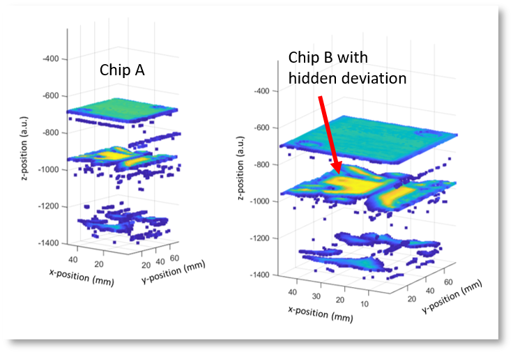
Application example: IC authenticity verification

Stacked interfaces and buried structures of an IC localized with the TSR.75 transceiver.
Sample ICs courtesy of Dr. Asadi’s group, Florida Institute for Cybersecurity Research (FICS). Stacked interface and buried structure localization with Protemics’ software package Teraloc, optimized for TeraSpike probes.
Highest resolution

TD-800-TSR-TT.75.

While basically all TR-series probes can also be used in transmission mode, the TSR-TT.75 is the best choice for it when the highest spatial resolution counts.

TD-800-TSR-TT.75 — surface scanning at maximum resolution

TeraSpike TD-800-TSR-TT.75 transceiver probe.
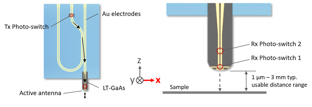
TSR-TT.75 cantilever design.
Measurement scheme of the TSR-TT.75: one antenna at normal incidence, usable in reflection and transmission.
One antenna at normal incidence — reflection and transmission.

Technical data · TSR-TT.75-PCA-PCS10-50

ParameterTSR-TT.75-PCA-PCS10-50
Max. spatial resolution40 µm
Dark current @ 1 V bias< 10 nA (typ. < 1.5 nA)
Photocurrent @ 1 V bias> 0.1 µA (typ. > 0.25 µA)
Excitation wavelength700–860 nm
Average excitation power0.1–3 mW
Connection type2 × SMP

Application example: thin-film inspection

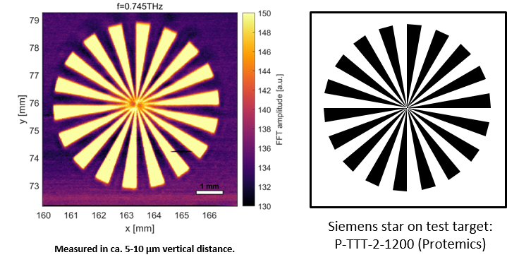
Thin-film inspection of the THz test target with the TSR-TT.75.
Terahertz test target P-TTT-2-1200 with Cr layers of 10 nm and 50 nm thickness — about 250 Ω and 50 Ω sheet resistance.

Each probe is individually tested and ships with a manual and test certificate. TR-series video on Vimeo ↗

Where it's used

When transmission is not an option.

Volume screening

Defects in opaque materials

Inspect laser welds, fiber-reinforced polymers and organic layers from one side only.

Chip testing

Package-level inspection

Reflection-mode measurements on chips and packages that block the transmitted THz beam.

Chip & package inspection →
Ready to specify

Request a transceiver quote.

Tell us about your sample and the depth you need to look into — we'll recommend the right TR geometry.